12 Results
View results:
Sort by:

The Construction Stages Analysis (CSA) add-on allows for the design of member, surface, and solid structures in RFEM 6 considering the specific construction stages associated with the construction process. This is important since buildings are not constructed all at once, but by gradually combining individual structural parts. The single steps in which structural elements, as well as loads, are added to the building are called construction stages, whereas the process itself is called a construction process.
Thus, the final state of the structure is available upon completion of the construction process; that is, all the construction stages. For some structures, the influence of the construction process (that is, all the individual construction stages) might be significant and it should be considered so that errors in the calculation are avoided. A general overview of the CSA add-on is given in the Knowledge Base article titled “Consideration of Construction Stages in RFEM 6”.

The calculation of complex structures by means of finite element analysis software is generally performed on the entire model. However, the construction of such structures is a process carried out in multiple stages where the final state of the building is achieved by combining the separate structural parts. To avoid errors in the calculation of overall models, the influence of the construction process must be considered. In RFEM 6, this is possible using the Construction Stages Analysis (CSA) add-on.

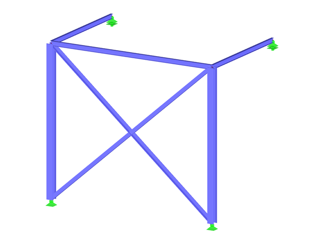
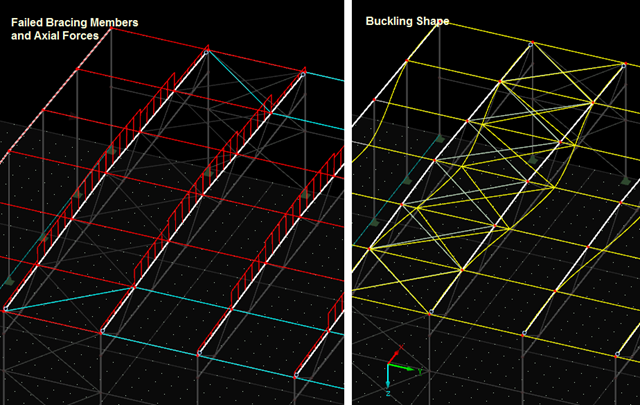
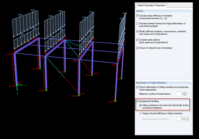
The most common causes of unstable models are failing member nonlinearities such as tension members. As the simplest example, there is a frame with supports on the column footing and moment hinges on the column head. This unstable system is stabilized by a cross bracing of tension members. In the case of load combinations with horizontal loads, the system remains stable. However, if it is loaded vertically, both tension members fail and the system becomes unstable, which causes a calculation error. You can avoid such an error by selecting the exceptional handling of failing members under "Calculate" → "Calculation Parameters" → "Global Calculation Parameters".
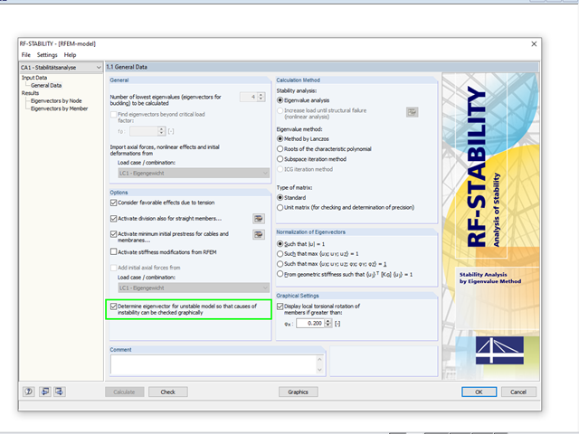
A calculation break‑off due to an unstable system can have different reasons. On one hand, it can indicate a "real" instability due to overloading of the system; on the other hand, the error message can result from inaccuracies in the model.
If the calculation of a member model according to the second-order analysis is terminated with an error message, this instability is often caused by failed tension members: As soon as compressive forces appear in a tension member during a calculation step, this member is no longer considered in the following iterations. Thus, the model can become unstable.
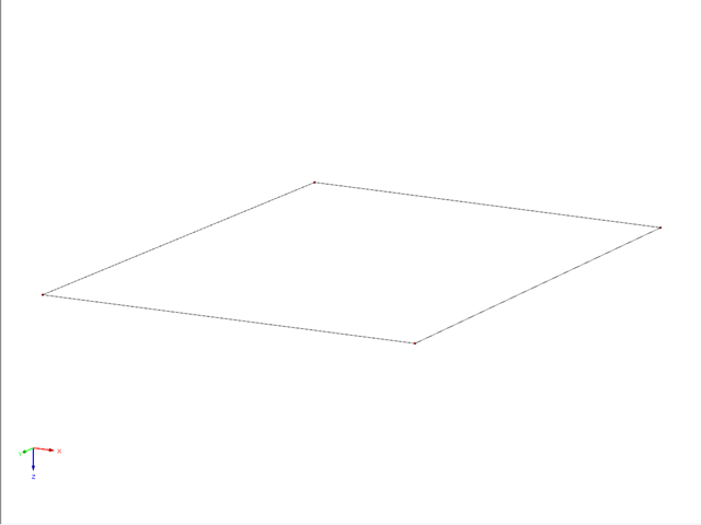
This example describes a definition of a planar surface by four nodes that have been imported and seem to lie in a common plane. In reality, they are not exactly in one plane due to (for example) a previous modeling error of a few millimeters. When trying to create a planar surface, the error message "Error in the surface definition! The nodes do not lie in a common plane." appears.

Shell buckling is considered to be the most recent and least explored stability issue of structural engineering. This is due less to a lack of research activities than to the complexity of the theory. With the introduction and further development of the finite element method in structural engineering practice, some engineers no longer have to deal with the complicated theory of shell buckling. Evidence of the problems and errors to which this gives rise is very well summarized in [1].
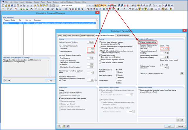
If nonlinearities are used in a model (for example, contact solids), an error message may appear at the end of the calculation due to the locally unfulfilled convergence criteria. The reason for this is that the convergence of the global iteration conditions governs in the calculation.
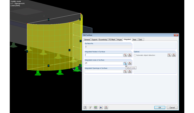
RFEM facilitates modeling by the automatic integration of objects into surfaces. However, it is impossible to integrate the objects automatically in the case of curved surfaces. For manual integration, select the relevant surfaces and click the "Edit Surfaces" option in the shortcut menu; then, in the "Integrated" tab, you can integrate the relevant objects using the "Select" function. This way, you can avoid error messages caused by non‑integrated objects when starting the calculation.
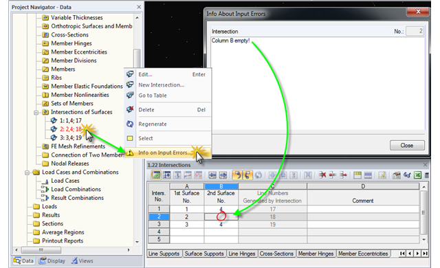
When modeling structural systems or loads, input errors or faulty objects may occur due to subsequent modifications, displacements, and adjustments in the model.
The previous post on this topic describes instabilities that may occur when using tension members. The example shown refers primarily to wall stiffening. Now, instability error messages can also refer to nodes within the range of supports. Truss girders and support trusses are especially susceptible to this. What causes the instability here?
Shoring braces usually obtain the "tension member" type. There are a few specifics to note because in the case of uniform, symmetrical structures and solely vertical loads, an error message often appears as follows: "The model is unstable in node No. 20. Free movement around Y-direction."